
EV
Table of Contents
Comprehensive Technical Guide: Next-Generation Smart EV Chargers & Intelligent Infrastructure
The shift toward zero-emission transportation is forcing a fundamental redesign of electrical infrastructure. As electric vehicle (EV) penetration grows, traditional “plug-and-forget” charging systems present severe risks to local power distribution, including grid congestion, voltage instability, phase imbalance, and transformer overloading.
Smart EV chargers address these challenges by replacing static power delivery with real-time, bi-directional data and energy management. Beyond simply delivering kilowatt-hours (kWh) to a battery, modern smart charging networks optimize load profiles, integrate localized renewable energy generation, enforce granular access controls, and allow electric vehicles to function as distributed energy resources (DERs) for grid stabilization.
1. Core Architecture of Smart EV Chargers
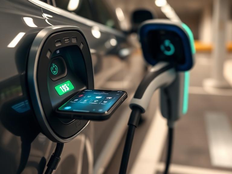
A smart EV charger—technically termed Electric Vehicle Supply Equipment (EVSE)—combines power electronics, embedded telemetry controllers, secure communication hardware, and cloud-native management platforms.
┌────────────────────────────────────────────────────────────────────────┐
│                   CLOUD / BACKEND ARCHITECTURE                         │
│  ┌──────────────────────────────────────────────────────────────────┐  │
│  │    Charging Station Management System (CSMS) / Software Platform  │  │
│  └──────────────────────────────────────────────────────────────────┘  │
└─────────────────────────────────┬──────────────────────────────────────┘
                                  │ OCPP 1.6 / 2.0.1 / 2.1 (WebSockets)
┌─────────────────────────────────┴──────────────────────────────────────┐
│                    SMART EV CHARGER (EVSE) HARDWARE                    │
│  ┌──────────────────────────────┐    ┌──────────────────────────────┐  │
│  │  Supply Equipment            │    │  Embedded Microcontroller    │  │
│  │  Communication Controller    │◄──►│  & Local Load Engine         │  │
│  │  (SECC)                      │    └──────────────┬───────────────┘  │
│  └──────────────┬───────────────┘                   │                  │
│                 │ ISO 15118 (PLC)                   │ Modbus / CT      │
│                 ▼                                   ▼                  │
│  ┌──────────────────────────────┐    ┌──────────────────────────────┐  │
│  │  High-Power Switching &      │    │  Smart Metering & Safety     │  │
│  │  Power Electronics           │    │  (MID Meter, RCD / GFCI)     │  │
│  └──────────────┬───────────────┘    └──────────────────────────────┘  │
└─────────────────┼──────────────────────────────────────────────────────┘
                  │ Control Pilot (PWM) & Power Line
                  ▼
┌────────────────────────────────────────────────────────────────────────┐
│                        ELECTRIC VEHICLE (EV)                           │
│  ┌──────────────────────────────────────────────────────────────────┐  │
│  │    Electric Vehicle Communication Controller (EVCC)              │  │
│  │    & On-Board Charger (OBC) / Battery Management System (BMS)    │  │
│  └──────────────────────────────────────────────────────────────────┘  │
└────────────────────────────────────────────────────────────────────────┘
Key Hardware & Embedded Components
Microcontroller Unit (MCU) & Telemetry Module
The brain of the charger, usually based on ARM Cortex-A or high-performance Cortex-M architectures. It runs an embedded Linux or FreeRTOS environment to execute local load balancing algorithms, manage cryptographic keys, process sensor telemetry, and handle communication protocols.
Supply Equipment Communication Controller (SECC)
A dedicated hardware module responsible for high-level communication with the car’s Electric Vehicle Communication Controller (EVCC). The SECC implements the HomePlug Green PHY Power Line Communication (PLC) physical layer required for high-bandwidth standard protocols.
Smart Metering (MID Compliant)
Integrated current transformers (CTs) or direct-pass digital power meters compliant with the Measuring Instruments Directive (MID). These meters continuously track active power (kW), reactive power (kVAR), voltage, current, and total energy consumption (kWh) with Class 1 or Class 0.5 accuracy for billing and load calculations.
Integrated Safety Architecture
Modern smart EV chargers include:
- Residual Current Monitoring (RCM): Detects both AC (30mA) and DC (6mA) leakage currents (IEC 62955) without requiring costly upstream Type B Residual Current Devices (RCDs).
- PEN Fault Detection: Integrated protective earth and neutral (PEN) conductors protection (crucial for single-phase TN-C-S grounding systems) to automatically isolate the vehicle if the supply neutral breaks.
- Thermal Management: Multi-point temperature sensors at contact relays, terminal blocks, and connector pins to throttle power if overheating occurs.
2. Advanced Communication Protocols & Standards
Interoperability across hardware, software, and vehicles depends on open standard protocols. Proprietary, closed systems create vendor lock-in and increase long-term technical debt.
┌──────────────────────────────────────────────────────────────────┐
│                   Open Charge Point Interface (OCPI)             │
│               (Roaming, Cross-Network Telemetry, Billing)         │
└────────────────────────────────┬─────────────────────────────────┘
                                 │
┌────────────────────────────────┴─────────────────────────────────┐
│              Open Charge Point Protocol (OCPP 2.0.1 / 2.1)       │
│               (Charger ↔ CSMS Management & Scheduling)          │
└────────────────────────────────┬─────────────────────────────────┘
                                 │
┌────────────────────────────────┴─────────────────────────────────┐
│                         ISO 15118-2 / ISO 15118-20               │
│               (Vehicle ↔ Charger High-Level Communication)        │
└────────────────────────────────┬─────────────────────────────────┘
                                 │
┌────────────────────────────────┴─────────────────────────────────┐
│                       IEC 61851-1 / SAE J1772                    │
│               (Basic Control Pilot Pulse Width Modulation)       │
└──────────────────────────────────────────────────────────────────┘
Protocol Comparison Matrix
| Protocol Level | Protocol Name | Primary Scope & Function | Key Features & Enhancements |
| EV-to-EVSE | IEC 61851-1 / SAE J1772 | Basic analog signaling via Control Pilot (CP) and Proximity Pilot (PP) pins. | Uses Pulse Width Modulation (PWM) duty cycles to communicate maximum allowable AC current. |
| EV-to-EVSE | ISO 15118-2 / -20 | Digital high-level communication over Power Line Communication (PLC). | Supports Plug & Charge, PKI security, dynamic load requests, and bidirectional power transfer (V2G). |
| EVSE-to-Cloud | OCPP 1.6J | Legacy standard for hardware-to-backend communication via WebSockets/JSON. | Basic remote start/stop, status reporting, simple smart charging profiles. |
| EVSE-to-Cloud | OCPP 2.0.1 / 2.1 | Modern open standard between EVSE and Charging Station Management Systems (CSMS). | Enhanced device management, native ISO 15118 support, advanced security profiles, and V2G control blocks. |
| Backend Roaming | OCPI (2.2.1 / 3.0) | Protocol connecting distinct Charge Point Operators (CPOs) and eMSPs. | Enables automated roaming session clearing, dynamic rate tables, tariff display, and remote booking. |
| Grid / Demand Response | OpenADR 2.0b / 3.0 | Utility-to-CSMS demand response protocol. | Communicates dynamic utility tariff signals, curtailment requests, and grid stress warnings. |
3. Dynamic Load Balancing (DLB) Mechanics
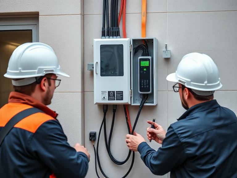
Installing multiple high-power chargers often exceeds a site’s electrical capacity. Dynamic Load Balancing (DLB) prevents blown fuses and circumvents costly main-fuse grid upgrades by measuring total site power in real time and adjusting charger outputs dynamically.
                 ┌───────────────────────────────────────┐
                 │       Grid Utility Supply (200 A)     │
                 └───────────────────┬───────────────────┘
                                     │
                        ┌────────────▼───────────┐
                        │ Main Distribution Board│
                        │   with CT Clamps       │
                        └────────────┬───────────┘
                                     │
           ┌─────────────────────────┴────────────────────────┐
           │                                                  │
┌──────────▼───────────┐                            ┌─────────▼──────────┐
│ Uncontrolled Building │                            │ Local DLB Master / │
│ Load (HVAC, Lights)   │                            │  Smart EV Chargers │
│ Variable: 40 A - 160 A│                            │ Dynamic: 160A - 40A│
└──────────────────────┘                            └─────────┬──────────┘
                                                              │
                                            ┌─────────────────┼─────────────────┐
                                            │                 │                 │
                                    ┌───────▼───────┐ ┌───────▼───────┐ ┌───────▼───────┐
                                    │ Smart Charger │ │ Smart Charger │ │ Smart Charger │
                                    │       #1      │ │       #2      │ │       #3      │
                                    └───────────────┘ └───────────────┘ └───────────────┘
Static vs. Dynamic Load Balancing
- Static Load Management: Allocates a fixed maximum current to a cluster of chargers regardless of overall facility consumption. If a site has a dedicated 100A allocation for 4 chargers, each charger is capped at 25A permanently, leaving available capacity unused when building demand is low.
- Dynamic Load Management: Employs Current Transformer (CT) clamps or Modbus/RS485 smart meters at the main incoming electrical panel. The local DLB engine samples total building demand multiple times per second and computes the remaining margin before adjusting the chargers:
$$\mathbf{I}_{\text{Available for EVs}} = \mathbf{I}_{\text{Main Fuse Rating}} – \mathbf{I}_{\text{Building Load}} – \mathbf{I}_{\text{Safety Margin}}$$
If total building load increases (e.g., HVAC compressors engage), the DLB controller issues real-time OCPP SetChargingProfile commands to lower EV charge currents within seconds. When building demand drops, charging speeds scale back up.
Multi-Tiered Load Balancing Architectures
- Local Hardwired DLB (RS485 / Ethernet): A master EVSE or external gateway measures local CT clamps and directly coordinates slave chargers over a Modbus/CANbus loop. This setup operates independently of internet connectivity, guaranteeing millisecond-level response times and complete protection against local network outages.
- Cloud-Based Network DLB: A cloud CSMS aggregates telemetry from smart meters and individual chargers over cellular/OCPP interfaces. This approach suits geographically distributed sites, though it requires fallback local safety profiles in case internet connectivity drops.
4. Vehicle-to-Grid (V2G) & Bidirectional Energy Flows
Bidirectional smart charging transforms electric vehicles from pure loads into active energy storage units.
The Bidirectional Topology Landscape
- V2G (Vehicle-to-Grid): Exports stored EV battery energy back to the distribution grid to relieve peak demand, provide frequency regulation, and earn financial credits.
- V2H (Vehicle-to-Home) / V2B (Vehicle-to-Building): Supplies off-grid or parallel power directly to a home or commercial building during peak tariff hours or grid blackouts.
- V2L (Vehicle-to-Load): Provides localized AC power directly from the vehicle’s onboard inverter to power external tools, electronics, or emergency gear.
                           ┌────────────────────────┐
                           │      Power Grid        │
                           └───────────▲────────────┘
                                       │
                               ┌───────▼────────┐
                               │ Smart Bi-Dir   │
                               │ DC Charger     │
                               └───────▲────────┘
                                       │
                ┌──────────────────────┴──────────────────────┐
                │                                             │
      ┌─────────▼─────────┐                         ┌─────────▼─────────┐
      │  Solar PV System  │                         │ EV Battery Pack   │
      │   (Generation)    │                         │  (Distributed)    │
      └───────────────────┘                         └───────────────────┘
The Role of ISO 15118-20 and OCPP 2.1
Older protocols lacked standard communication mechanisms to coordinate reverse power flows. ISO 15118-20 introduces native bidirectional message formats, allowing the vehicle’s Battery Management System (BMS) to report discharge limits, state-of-charge (SoC) curves, degradation limits, and minimum driver energy targets.
Simultaneously, OCPP 2.1 provides specific functional blocks for Bidirectional Energy Flow control and Distributed Energy Resource (DER) management. The backend system can issue dynamic operational schedules, commanding the charger to switch seamlessly between charging, holding, and discharging back to the site or grid.
5. Plug & Charge Security Infrastructure (ISO 15118 PKI)
Historically, public charging required RFID keyfobs, credit card swipers, or mobile apps. Plug & Charge (P&C), defined under ISO 15118, automates authentication and payment: the driver simply inserts the charging cable, and charging begins automatically.
┌─────────────────┐      1. Connect Cable & TLS Handshake     ┌─────────────────┐
│                 ├──────────────────────────────────────────►│                 │
│                 │      2. Send Contract Certificate         │                 │
│                 ├──────────────────────────────────────────►│                 │
│   EV (EVCC)     │                                           │ Smart EVSE      │
│                 │      3. Verify Certificate Chain via PKI  │  (SECC)         │
│                 │◄──────────────────────────────────────────┤                 │
│                 │      4. Encrypted Session Authorized      │                 │
└─────────────────┘                                           └────────┬────────┘
                                                                       │
                                                                       │ 5. Authorize (OCPP)
                                                                       ▼
                                                              ┌─────────────────┐
                                                              │  CSMS / Mobility│
                                                              │  Clearinghouse  │
                                                              └─────────────────┘
Public Key Infrastructure (PKI) Architecture
Plug & Charge relies on an asymmetric Public Key Infrastructure (PKI) using TLS 1.3 encryption to establish trusted relationships among several stakeholders:
- V2G Root CA: The top-level Certificate Authority that anchors trust across the ecosystem.
- OEM Provisioning Certificate (OEM PC): Installed in the vehicle during manufacturing to verify vehicle identity.
- Contract Certificate: Issued by the eMobility Service Provider (eMSP) and stored securely in the vehicle’s hardware security module (HSM). It links the vehicle directly to the user’s billing account.
- CPO Sub-CA & Leaf Certificates: Installed on the SECC of the smart charger to enable mutual TLS authentication between the car and the charger.
When the cable connects, an encrypted mTLS session forms over Power Line Communication. The charger reads the vehicle’s Contract Certificate, validates it against the Certificate Revocation List (CRL) via OCPP 2.0.1/2.1, and initiates the session—all within seconds and without manual user intervention.
6. Real-World Deployment Scenarios & Topologies
┌────────────────────────────────────────────────────────────────────────────────────────┐
│                                DEPLOYMENT MATRIX                                       │
├───────────────────┬──────────────────────────┬───────────────────────┬─────────────────┤
│ Feature           │ Multi-Residential (HOA)  │ Commercial Workplace  │ Fleet Depot     │
├───────────────────┼──────────────────────────┼───────────────────────┼─────────────────┤
│ Topology          │ Multi-drop AC Wallboxes  │ Dual-Gun AC/DC Chargers│ High-Power DC   │
├───────────────────┼──────────────────────────┼───────────────────────┼─────────────────┤
│ Dominant Protocol │ OCPP 2.0.1 + Modbus DLB  │ OCPP 2.0.1 + OCPI     │ OCPP 2.1 + V2G  │
├───────────────────┼──────────────────────────┼───────────────────────┼─────────────────┤
│ Billing Method    │ Individual Sub-metering  │ RFID / Corporate App  │ Fleet Telematics│
├───────────────────┼──────────────────────────┼───────────────────────┼─────────────────┤
│ Core Objective    │ Peak Shaving & Equity    │ Solar Self-Consumption│ Schedule Readiness│
└───────────────────┴──────────────────────────┴───────────────────────┴─────────────────┤
Multi-Residential / Apartment Complexes (HOA)
- Challenge: Limited main panel capacity shared among hundreds of residents, requiring fair power distribution and individual billing accuracy.
- Topology: A network of 7.4 kW to 22 kW smart AC wallboxes linked via a local Ethernet ring to a master DLB controller.
- Execution: Dynamic load management ensures total current never exceeds the building main fuse. MID-certified sub-metering tracks individual consumption, while OCPP pushes session records to a cloud billing system for automated tenant invoicing.
Commercial Workplace & Retail Hubs
- Challenge: High daytime energy demand coupled with volatile electricity pricing and demand charges.
- Topology: A mix of dual-socket 22 kW AC chargers and 50–150 kW DC fast chargers paired with a rooftop Solar PV system and Battery Energy Storage System (BESS).
- Execution: The smart charging platform monitors local solar generation and adjusts charger outputs to absorb solar overproduction. During grid peak hours, the system throttles charger output to keep peak demand below utility thresholds, reducing demand charges.
Fleet Depots (Logistics & Transit)
- Challenge: Tight turnaround schedules requiring precise state-of-charge targets by departure time, without triggering massive utility demand charges.
- Topology: High-power DC fast charging cabinets (150 kW–400 kW) with liquid-cooled cables and automated overhead pantographs for heavy-duty buses or trucks.
- Execution: Integrates fleet scheduling software with OCPP 2.1 via API. The system prioritizes vehicles based on departure times and route energy demands, dynamically cycling charge rates to deliver required energy at the lowest overall cost.
7. Troubleshooting & Diagnostic Workflows
Operating a smart EV charging network requires structured diagnostic tools to resolve hardware, network, and protocol issues quickly.
                  ┌────────────────────────────────────────┐
                  │ Issue Detected: Charging Session Fails │
                  └───────────────────┬────────────────────┘
                                      │
                         ┌────────────▼───────────┐
                         │ Perform Physical Safety│
                         │    & Voltage Inspection│
                         └────────────┬───────────┘
                                      │
            ┌─────────────────────────┴─────────────────────────┐
            │ OK                                                │ Fault
┌───────────▼────────────┐                            ┌──────────▼───────────┐
│ Inspect Control Pilot  │                            │ Clear Fault & Check  │
│ (CP) Duty Cycle Signal │                            │ Grounding / RCD      │
└───────────┬────────────┘                            └──────────────────────┘
            │ 12V -> 9V -> 6V Sequence Valid
┌───────────▼────────────┐
│ Check Network / OCPP   │
│ WebSocket Connectivity │
└───────────┬────────────┘
            │ Online
┌───────────▼────────────┐
│ Analyze ISO 15118 /    │
│ PKI TLS Certificates   │
└────────────────────────┘
Step-by-Step Diagnostic Protocol
- Physical & Pilot Signal Inspection: Verify physical interlocks and measure the Control Pilot (CP) line voltage using an oscilloscope or EVSE simulator.
- State A: +12V (Disconnected)
- State B: +9V (Vehicle Connected)
- State C: +6V (Charging Requested – Contactors Closed)
- State D: +3V (Ventilation Required)
- Local Loop & Power Quality Checks: Inspect supply voltage line-to-line and line-to-neutral under load. Verify phase rotation and check for neutral-to-ground voltage leakage. Confirm that local CT clamps are correctly oriented and transmitting accurate Modbus telemetry to the DLB engine.
- OCPP Connectivity & Logging Analysis: Examine local charger log files or CSMS telemetry streams for error codes. Common status flags include:
GroundFailure: Tripped RCD or missing protective earth bond.HighTemperature: Thermal throttling triggered by terminal degradation or loose wiring.OverCurrentFailure: Vehicle drew power exceeding the maximum limits negotiated via OCPPSetChargingProfile.
- ISO 15118 & PKI TLS Handshake Verification: If Plug & Charge fails, inspect the SECC logs to verify the mTLS handshake. Ensure that the charger’s system clock is synchronized via NTP, as clock drift causes premature expiration errors on PKI contract certificates.
8. Frequently Asked Questions (FAQs)
Q1: What makes an EV charger “smart” compared to a standard charger?
A standard charger (dumb EVSE) simply acts as a high-power switch, supplying unmanaged AC power as soon as a vehicle plugs in. A smart EV charger includes built-in microcontrollers, smart metering, and data connectivity (Wi-Fi, Cellular, Ethernet). This allows it to communicate with a cloud platform (CSMS), adjust charge rates in real time based on grid conditions, run dynamic load balancing, automate billing, and allow remote diagnostics.
Q2: How does Dynamic Load Balancing prevent circuit breakers from tripping?
Dynamic Load Balancing uses smart meters or CT clamps installed at the main electrical panel to measure total site consumption in real time. The system calculates available capacity by subtracting current building consumption from the main fuse limit. It then continuously adjusts the power delivered to connected EVs via OCPP or local control loops, keeping total demand within safe operating limits.
Q3: What is the difference between OCPP 1.6 and OCPP 2.0.1 / 2.1?
OCPP 1.6 handles basic session management and smart charging profiles. OCPP 2.0.1 and 2.1 add advanced remote device management, enhanced security profiles, ISO 15118 integration for Plug & Charge, dynamic display messaging, and native support for bidirectional power flow (V2G).
Q4: What is ISO 15118, and why is it important for modern EV infrastructure?
ISO 15118 is an international standard governing digital communication between an electric vehicle and a charger over the charging cable. It enables Plug & Charge—which automates authentication and billing without apps or RFID cards—as well as dynamic smart charging and Vehicle-to-Grid (V2G) bidirectional power flows.
Q5: Can I install multiple smart EV chargers on a constrained electrical service?
Yes. With Dynamic Load Balancing, you can deploy multiple smart chargers on an existing panel without paying for an electrical service upgrade. The chargers dynamically share available power, throttling or queuing charging sessions during peak building usage and ramping back up when demand drops.
Q6: What is Vehicle-to-Grid (V2G), and how does it work?
V2G is a bi-directional charging capability that lets an EV export energy from its battery pack back to the power grid or building. Controlled via ISO 15118-20 and OCPP 2.1 protocols, V2G helps stabilize the grid during peak demand hours, provides emergency backup power, and allows fleet operators to monetize stored energy.
Q7: What happens if a smart EV charger loses its internet connection?
High-quality smart chargers use local fallback profiles. If cloud connectivity drops, the charger reverts to a safe, pre-programmed charging limit (or continues local Modbus/RS485-based load balancing) to prevent panel overloads while ensuring connected vehicles still receive a charge.
Q8: How does Plug & Charge authenticate a vehicle without an app or RFID card?
When connected, the vehicle and charger establish an encrypted TLS session over Power Line Communication (PLC). The vehicle securely transmits an encrypted Contract Certificate issued by its mobility provider. The charger validates this certificate against a trusted Certificate Authority (PKI) via the backend system and starts charging automatically.
Q9: What is the role of CT clamps in smart charging installations?
Current Transformer (CT) clamps clip around the main incoming electrical lines to measure current draw in real time. They pass these readings to the smart charger or local load manager, enabling dynamic adjustments to charging speeds based on household or building demand.
Q10: How do smart chargers integrate with solar panels (PV)?
Smart EV chargers can monitor solar inverter production via Modbus, direct APIs, or CT clamps. They can be set to “Solar Sponge” or “Eco” modes, which automatically match EV charge rates to real-time solar overproduction, maximizing self-consumption and preventing free solar energy from being exported to the grid at low feed-in rates.
Q11: What is the difference between AC and DC smart EV charging?
AC chargers (Level 1 and Level 2) deliver alternating current to the vehicle’s onboard charger (OBC), which converts it to DC for battery storage. DC fast chargers bypass the vehicle’s onboard converter to feed direct current straight to the battery at much higher speeds (50 kW to 400+ kW). Both can incorporate smart management software, though DC chargers require heavier high-power conversion hardware.
Q12: Why is MID meter compliance necessary for commercial smart chargers?
The Measuring Instruments Directive (MID) is an EU standard ensuring that electrical meters meet strict accuracy guidelines. MID compliance is legally required for commercial and multi-family EV chargers that charge users based on exact kilowatt-hour (kWh) usage, ensuring legally defensible billing data.
Q13: What security risks affect connected EV chargers, and how are they mitigated?
Connected chargers can face risks like unauthorized access, firmware tampering, and intercepted communications. Modern standards like OCPP 2.0.1 and ISO 15118 address these by enforcing mutual TLS encryption, secure boot routines, signed firmware updates, and isolated hardware security modules (HSMs).
Q14: How does dynamic pricing work with smart EV chargers?
Dynamic pricing links charging tariffs to real-time wholesale electricity markets or utility Time-of-Use (TOU) rates. Smart charging platforms automatically schedule charging sessions during the cheapest off-peak hours (e.g., overnight or during high renewable production) to minimize total charging costs.
Q15: What infrastructure is required to deploy a fleet smart charging network?
A fleet smart charging network requires:
- High-power AC wallboxes or DC fast chargers equipped with OCPP 2.0.1/2.1.
- Dedicated, high-speed networking (Ethernet or dual-SIM cellular gateways).
- Integrated MID-certified metering or vehicle telematics connections.
- A central Charging Station Management System (CSMS) capable of dynamic load management, automated schedule optimization, and fleet telematics integration.